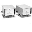
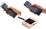
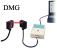
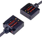
BNC (Data Transfer Checker)

Optical data transmission device
Parallel type
|
BNC-HB1 |
Data Transfer Checker |

|
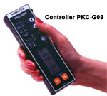
Data transfer checker can check the interlocking on SEMI E84 beforehand ! Data transfer checker provides the following 2 kinds of application software(Hokuyo Data Flex SFOC and RIS). 1. Hokuyo Data Flex SFOC When some troubles such as interlocking etc. happened, memorized data(Communication data) can be read out from DMG series and its data can be displayed on PC. Refer to the above(1)about correspondent devices. 2. Hokuyo Data Flex RIS Under automatic transportation system on semiconductor and LCD manufacturing facilities, it is possible to make data communication as imaginary UTV(AGV, RGV, OHT etc.) or fixed passive equipments on the interlocking system with parallel I/O between UTV and passive equipments. Refer to the above(2)about correspondent devices. |

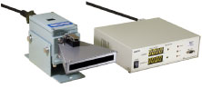
Structures
Data transfer checker consists of the following proucts:
- BNC-HB1 Head : 1 pce
- EPK-BNC1 Power box : 1 pce
- AC adaptor with cable 2m : 1 pce
- Cable 300mm for BNC-HB1(for PC connector) : 1 pce
- Application software(SFOC/RIS) : 1pce
Specifications
|
BNC-HB1 Head |
Model No. |
BNC-HB1(with cable 300mm) |
|
Direction |
SIDE-ON |
|
|
Transmission distance |
300mm |
|
|
EPK-BNC1 |
Model No. |
EPK-BNC1 |
|
Power source |
Built-in rechargeable battery(Charging from AC Adaptor) |
|
|
Battery life |
Approx. 4 hours(When continuous use) |
|
|
Charging time |
Approx. 16 hours |
|
|
Cable for BNC-HB1 |
300mm EIA-574(RS-232C 9 pins connector)*1 |
|
|
BNC-HB1 |
Hokuyo Data Flex SFOC |
Communication data(Logging data) is read out from DMG series |
|
Hokuyo Data Flex RIS |
It is possible to make data communication as imaginary UTV(AGV, RGV, OHT etc.) or fixed passive equipments under automatic transportation system. |
|
*1 Cable length between BNC-HB1 Head and PC should be within 6m.
*2 Ask about the details of specifications.
External dimension
|
|
||||
|


* This device is compatible with DMS series and DM series which was discontinued to produce since Sep.'01.
More Info PriceDMG(with data logging function)
|
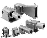
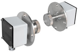
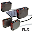
Optical Data Transmission Devices PARALLEL TYPEDMG |
|
|
|
Useful to solve some troubles such as interlocking! When some troubles such as interlocking etc. happened, memorized data(Logging data) in DMG series can be read out by optical remote controller type, Data Transfer Checker(Option). Also its data can be displayed on PC by application software(SFOC). |


Specifications
| Type | Parallel type | |||
| 8-bit type | ||||
|
Model No. |
DMG-GB1 |
DMG-GB2 |
DMG-HB1 |
DMG-HB2 |
|
Direction |
HEAD-ON |
SIDE-ON |
||
|
Transmission distance * |
0 to 1m |
0 to 3m |
0 to 1m |
0 to 3m |
|
Directional angle |
30° |
10° |
30° |
10° |
|
Transmission |
Half-duplex two-way transmission |
|||
|
Transmission time |
40ms |
|||
|
Modulation method |
Pulse modulation |
|||
|
Detection method |
Parity check |
|||
|
Power source |
DC10 to 30V(allowable voltage) |
|||
|
Current consumption |
100mA or less |
|||
|
Ambient illuminance |
4,000lux or less(Incandescent lamp) |
|||
|
Ambient temperature/ humidity |
-10 to +50° C, 85%RH or less |
|||
|
Vibration resistance |
Double amplitude 1.5mm, 10 to 55Hz, each 2 hour in X, Y and Z directions |
|||
|
Impact resistance |
500m/s2, each 10 time in X, Y and Z directions |
|||
|
Connection |
500m/s2, each 10 time in X, Y and Z directions |
|||
|
Protective structure |
IP64(IEC standard) |
|||
* It can be adjusted.
Transmission area

External dimension

Input/output circuit
|
Input |
Output |
|
|
|
|
Contact or open-collector Note) Don't use the sensor with 2-wire(Operating threshold current 1.5 to 2mA) |
NPN open-collector output |


Connection

|
|
|||||||||||||||||||||||||||||||||||||||||||||||||||||||||||||||||||||||||||||||||
*1 MODE input
This is to choose transmission/reception mode when standing by
*Transmission stand-by mode by opened between mode and I/O COM
*Reception stand-by mode by short-circuited between mode and I/O COM
*2 SELECT input
This is to stop transmission/reception optionally by outer signal
*Operating by opened between select and I/O COM
*Stopping by short-circuited between select and I/O COM
*3 GO output
This is to check correct optical single
*ON when receiving correct optical axis
*OFF when interrupting optical axis(Not-receiving)
Note) Cable ends for unused input/output, GO output, SELECT input, MODE input, NC(4-bit type) should be processed individually and don't connect with other cable. It may cause unstable operation if package processing.
Note) Don't use the connector attached to the cables as connecting terminal.
Note) If one side is set to transmission stand-by mode, other one should be set to reception standby mode.
Note) It is short-circuited between COM & -VIN inside.
* This device is compatible with DMS series and DM series which was discontinued to produce since Sep.'01.
More Info PriceDMH-GB/HB(high speed type)

|
Optical Data Transmission Devices PARALLEL TYPEDMH-GB/HB |
Optical Data Transmission Devices |
|
|
This device is high-speed type, data transmission device. |

Specifications
|
Type |
Parallel type |
|||
|
8-bit type |
||||
|
Model No. |
DMH-GB1 |
DMH-GB2 |
DMH-HB1 |
DMH-HB2 |
|
Transmission capacity(I/O) |
8BIT/8BIT |
|||
|
Direction |
HEAD-ON |
SIDE-ON |
||
|
Transmission distance |
0.6m |
3m |
0.6m |
3m |
|
Directional angle |
±15° |
±5° |
±15° |
±5° |
|
Transmission method |
Half-duplex two-way transmission |
|||
|
Transmission time |
7msec |
|||
|
Modulation method |
FSK modulation |
|||
|
Detection method |
Bit-reverse comparison system |
|||
|
Power source |
18 to 30VDC(ripple 10% or less) |
|||
|
Current consumption |
100mA Max. |
|||
|
Ambient illuminance |
10,000lux or less |
|||
|
Ambient temperature/ humidity |
-10 to +50 degrees C, 85%RH or less |
|||
|
Vibration resistance |
Double amplitude 1.5mm, 10 to 30Hz, each 2 hour in X, Y and Z directions |
|||
|
Impact resistance |
500m/s2, each 10 time in X, Y and Z directions |
|||
|
Connection |
Lead wire (0.2mm2, 26 cores, shield cable 2m long) |
|||
|
Protective structure |
IP64(IEC standard) |
|||
External dimension
DMH-GB1, DMH-GB2(HEAD-ON type)

DMH-HB1, DMH-HB2(SIDE-ON type)

Input/output circuit
Input

Flow current when ON(IO) : approx. 5mA(when 24VDC)
Allowable residual voltage when ON : use it with 1.8V or less
Output


NPN open-collector output
35DC 50mA residual voltage 1.5V or less
|
|
|||||||||||||||||||||||||||||||||||||||||||||||||||||||||||||||||||||||||||||||||||||||||||||
*1 MODE input
This is to choose transmission/reception mode when standing by
*Transmission stand-by mode by opened between mode and I/O COM
*Reception stand-by mode by short-circuited between mode and I/O COM
Note) If one side is set to transmission stand-by mode, other one should be set to reception standby mode.
*2 SELECT input
This is to stop transmission/reception optionally by outer signal
*Operating by opened between select and I/O COM
*Stopping by short-circuited between select and I/O COM
*3 GO output
This is to check correct optical single
*ON when receiving correct optical axis
*OFF when interrupting optical axis(Not-receiving)
Note) Don't use the connector attached to the cables as connecting terminal.
Note) Don't use (BSY), (MS) and (RDY).
DMH-GC/HC(16 bit, high speed type)

DMH-GC/HC (16 bit, high speed type)
Optical data transmission device
Parallel type
This device is high-speed type, data transmission device with 16 bits.
This device is smaller size and lighter weight than old type. This device provides light-projecting amount adjuster and so it is easy to adjust the communication distance.
Specifications
|
Type |
Parallel type |
|
|
16-bit type |
||
|
Model No. |
DMH-GC1 |
DMH-HC1 |
|
Transmission capacity(I/O) |
16BIT/16BIT |
|
|
Direction |
HEAD-ON |
SIDE-ON |
|
Transmission distance |
0 to 3m(can be adjusted by adjuster) |
|
|
Directional angle |
±13° |
|
|
Transmission method |
Half-duplex two-way transmission |
|
|
Transmission time |
15ms |
|
|
Modulation method |
FSK modulation |
|
|
Detection method |
Bit-reverse comparison system |
|
|
Power source |
DC18 to 30V(ripple 10% or less) |
|
|
Current consumption |
150mA Max. |
|
|
Ambient illuminance |
10,000lux or less |
|
|
Ambient temperature/humidity |
-10 to +50 degrees C, 85%RH or less |
|
|
Vibration resistance |
Double amplitude 1.5mm, 10 to 55Hz, each 2 hour in X, Y and Z directions |
|
|
Impact resistance |
500m/s2, each 10 time in X, Y and Z directions |
|
|
Connection |
Lead wire (0.2mm2, 40 cores, shield cable 2m long) |
|
|
Protective structure |
IP64(IEC standard) |
|
|
Weight |
Approx. 400g(including the cable 2m) |
|
D-sub connector type and long distance type(15m) are lined-up.
External dimension
DMH-GC1(HEAD-ON type)

DMH-HC1(SIDE-ON type)

* Mode changeover switch : If one is set to T side(transmission priority mode), other one have to be set to R side(reception priority mode).
Input/output circuit
Input

Flow current when ON(IO) : approx. 5mA(when 24VDC)
ON voltage : 2V or less, OFF voltage : 8V or more
Output


NPN open-collector output
35DC 50mA residual voltage 0.9V or less
Connection
 |
|
|
|
||||||||||||||||||||||||||||||||||||||||||||||||||||||||||||||||||||||||||||||
|
Connector (3) |
||
|
Colors |
Pin No. |
Functions |
|
Orange(red 1) |
1 |
IN6 |
|
Orange(red 2) |
2 |
OUT6 |
|
Orange(red 3) |
3 |
IN5 |
|
Orange(red 4) |
4 |
OUT5 |
|
Orange(black 1) |
5 |
IN4 |
|
Orange(black 2) |
6 |
OUT4 |
|
Orange(black 3) |
7 |
IN3 |
|
Orange(black 4) |
8 |
OUT3 |
|
Yellow(red 1) |
9 |
IN2 |
|
Yellow(red 2) |
10 |
OUT2 |
|
Yellow(red 3) |
11 |
IN1 |
|
Yellow(red 4) |
12 |
OUT1 |
|
Yellow(black 1) |
13 |
SELECT*1 |
|
Yellow(black 2) |
14 |
GO*2 |
|
Yellow(black 3) |
15 |
STROBE*3 |
Note) Don't use White(black4), gray(black4) and Yellow(black4). If cable is cut on the way, cut it at the base.
Note) Don't use the connector attached to the cables as connecting terminal.
*1 SELECT input
This is to stop transmission/reception optionally by outer signal
*Operating by opened between select and I/O COM
*Stopping by short-circuited between select and I/O COM
*2 GO output
This is to check correct optical single
*ON when receiving correct optical axis
*OFF when interrupting optical axis(Not-receiving)
*3 STROBE
ON when data is fixed.
DMS(compact model)
|
Optical data transmission device Parallel type DMS Compact model |
|
|
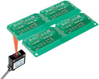
This device is parallel type, data transmission device with infrared ray. This is small size and right weight with 50×50×20mm. It is suitable for data transmission such as interlocking with carrier robots, indicating destination of AGV’s. This device provides light-projecting amount adjuster and so area adjustment can be made by it. |
Specifications
|
Type |
Parallel type |
|||||||||||||||||||||||
|
4-bit type |
8-bit type |
|||||||||||||||||||||||
|
Model No. |
|
|
|
|
|
|
|
|
||||||||||||||||
|
Transmission distance |
0 to 1m |
0 to 3m |
0 to 1m |
0 to 3m |
0 to 1m |
0 to 3m |
0 to 1m |
0 to 3m |
||||||||||||||||
|
Directional angle (Full angle) |
30° |
10° |
30° |
10° |
30° |
10° |
30° |
10° |
||||||||||||||||
|
Transmission method |
Half-duplex two-way transmission |
|||||||||||||||||||||||
|
Transmission time |
40msec or less |
|||||||||||||||||||||||
|
Modulation method |
Pulse modulation |
|||||||||||||||||||||||
|
Detection method |
Parity check |
|||||||||||||||||||||||
|
Power source |
24VDC(10 to 30VDC) |
|||||||||||||||||||||||
|
Input |
Contact or open-collector(ON current 2.5mA or more, |
|||||||||||||||||||||||
|
Output |
NPN open-collector(35VDC, 50mA or less, Residual voltage 1.8V or less) |
|||||||||||||||||||||||
|
Current consumption |
100mA Max. |
|||||||||||||||||||||||
|
Ambient illuminance |
4,000lux or less(Incandescent lamp) |
|||||||||||||||||||||||
|
Ambient temperature/humidity |
-10 to +50° C, 85%RH or less |
|||||||||||||||||||||||
|
Impact resistance |
500m/s2, each 10 time in X, Y and Z directions |
|||||||||||||||||||||||
|
Connection |
Lead wire 2m long |
|||||||||||||||||||||||
|
Protective structure |
IP64(IEC standard) |
|||||||||||||||||||||||
DMS-GA1-C/HA1-C which can be communicated with old type, DM-GA1/HA1 are lined-up.
External dimension
DMS-HA1-V/HA2-V, DMS-HB1-V/HB2-V(SIDE-ON type)

DMS-GA1-V/GA2-V, DMS-GB1-V/GB2-V(HEAD-ON type)

Input/output circuit
Input

ON current 2.5mA or more,
OFF current 1mA or less,
Note) Don't use the sensor with 2-wire.
Operating threshold current 1.5 to 2mA
Output


NPN open-collector output
35VDC 50mA
Residual voltage 1.8V or less
Connection
DMS-GA1-V/GA1-V, DMS-HA1-V/HA2-V(4-bit type)

|
Colors |
Pin No. |
Functions |
|
Black |
1 |
IN1 |
|
Brown |
2 |
IN2 |
|
Brown |
3 |
IN3 |
|
Orange |
4 |
IN4 |
|
White/yellow |
5 |
MODE*1 |
|
Yellow |
6 |
SELECT*2 |
|
White/blue |
7 |
NC |
|
Green |
8 |
OUT1 |
|
Blue |
9 |
OUT2 |
|
Purple |
10 |
OUT3 |
|
Gray |
11 |
OUT4 |
|
White |
12 |
GO*3 |
|
Yellow/green |
13 |
COM(0V) |
|
Yellow/red |
14 |
+VIN |
|
Yellow/black |
15 |
-VIN(0V) |
|
Shield |
Shield |
|
DMS-GB1-V/GB2-V, DMS-HB1-V/HB2-V(8-bit type)

|
|
|||||||||||||||||||||||||||||||||||||||||||||||||||||||||||||||||||||||||||||||||
*1 MODE input
This is to choose transmission/reception mode when standing by
*Transmission stand-by mode by opened between mode and I/O COM
*Reception stand-by mode by short-circuited between mode and I/O COM
*2 SELECT input
This is to stop transmission/reception optionally by outer signal
*Operating by opened between select and I/O COM
*Stopping by short-circuited between select and I/O COM
*3 GO output
This is to check correct optical single
*ON when receiving correct optical axis
*OFF when interrupting optical axis(Not-receiving)
Note) Cable ends for unused input/output, GO output, SELECT input, MODE input, NC(4-bit type) should be processed individually and don't connect with other cable. It may cause unstable operation if package processing.
Note) Don't use the connector attached to the cables as connecting terminal.
Note) If one side is set to transmission stand-by mode, other one should be set to reception standby mode.
|
Caution
|
I/O direction is appeared in accordance with DMS. |
HOKUYO MARKASINA A?T ?R?N GRUPLARI